HomeTurtlegraficsGPanelRobotics WebTigerPython
 Python - Online
lidar
Deutsch   English   

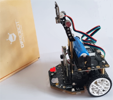
10. LIDAR, PID and LIGHTSensor (mbrobot plusV3)


YOU LEARN HERE...


how to use the advanced functions of the mbRobot Plus V3. In addition to the functions described in the previous chapters, the latest Maqueen model Plus V3 has the following enhancements:

  • LIDAR: Matrix laser distance sensor
  • PID Control: Motor encoder and PID control
  • Light sensor: Light intensity sensor
  • Crossing detection


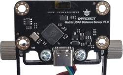
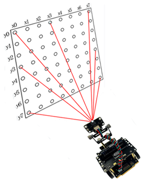
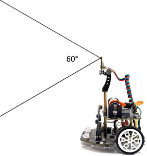
HOW DOES LIDAR WORK?

 
Lidar is a technology that uses laser light to measure distance. Lidar works similarly to an ultrasonic sensor. Instead of ultrasonic waves, it emits laser pulses that are reflected by objects. The time it takes for the light to travel there and back is measured. The distance is calculated using this time and the speed of light.  

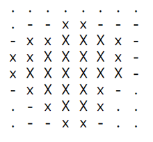
Maqueen Plus V3 is equipped with a matrix lidar sensor. Within a 60-degree detection range, it provides a matrix with 64 measured values.


You can use the following functions for distance measurement:

getDistance() returns the ‘direct’ distance to the object
getDistanceList() returns a list with 64 distance values
getDistanceGrid() returns 8 lists with 8 distance values each
getDistanceRow(i) returns distance values in the i-th row of the matrix
getDistanceColumn(j) returns distance values in the jth column of the matrix
getDistanceAt(x, y) returns the distance to point (x, y) of the matrix


EXAMPLES


Example 1: Detecting objects
Connect the lidar sensor to the first or second I2C interface. The robot moves forward and uses the lidar to measure the distance to the objects in front of it. You use the getDistance() command. If an object is closer than 20 cm, the robot stops. When the distance increases again, it starts moving again. The measured values are displayed with print(). delay(100) specifies the measurement period.


Program:

from mbrobot_plusV3 import *

setSpeed(30)
repeat:
    d = getDistance()
    print(d)
    if d < 20:
        stop()
    else:
        forward()    
    delay(100)
► Copy to clipboard


Example 2: Compare Lidar measurements on the left and right

The command getDistanceRow(4) returns a list of 8 measurements (the fourth row of the matrix). You compare the measurements on the left and right. If the distance on the left is smaller, the left LED lights up red; if the distance on the right is smaller, the right LED lights up green.
print(row) displays all 8 measurements. Place the object in different positions and observe the measurements.


Program:

from mbrobot_plusV3 import *

repeat:
    row = getDistanceRow(4) #8 Values left to right
    print(row)

    if row[0] < row[7]:
        setLEDLeft(1)
        setLEDRight(0)    
    else:
        setLEDLeft(0)
        setLEDRight(2)      
    delay(100)
► Copy to clipboard


Example 3: What does the LIDAR sensor ‘see’?

LIDAR sensor typically provides 8×8 = 64 measurement points. You can read these out with the command getDistanceList()and visualise them in 8 lines of 8 characters each. The closer a point is, the larger the character you select.

To make the matrix easier to view, select a longer measurement period (delay(3000)).


Program:

from mbrobot_plusV3 import *

def readData():
    data = getDistanceList()
    matrix = []
    for row in range(8):
        rowData = [data[row * 8 + col] for col in range(8)]
        matrix.append(rowData)
    return matrix

def showMap(matrix):
    for row in matrix:
        line = ""
        for val in row:
            if val < 30:
                line += " X "
            elif val < 60:
                line += " x "
            elif val < 100:
                line += " - "
            elif val < 150:
                line += " . "
            else:
                line += " "
        print(line)
    print("")    
    print("------------------------------")
    print("")
	
while True:
    matrix = readData()
    showMap(matrix)
    delay(3000)	
► Copy to clipboard


PID CONTROL


Maqueen Plus V3 has a motor encoder that allows you to precisely control the robot's forward movement and steering angle.
With the command pidControlDistance(dir, dist, 1)you can travel a distance dist specified in centimetres forwards (dir = 1) or backwards (dir = 2).
With the command pidControlAngle(angle, 1), the robot turns to the left (angle > 0) or right (angle < 0) by the given angle.


EXAMPLE


EXAMPLE 1: Driving and turning with PID control
The robot first moves 20 cm forwards, then 20 cm backwards, turns 90° to the left and then 90° to the right.

Program:

from mbrobot_plusV3 import *

pidControlDistance(1, 20, 1)
pidControlDistance(2, 20, 1)
pidControlAngle(90, 1)
pidControlAngle(-90, 1)
► Copy to clipboard

pidControlDistance(1, 20, 1) : the robot moves 20 cm forward.
pidControlDistance(2, 20, 1) : the robot moves 20 cm backward.
pidControlDistance(90, 1) : the robot turns 90° to the left.
pidControlDistance(-90, 1) : the robot turns 90° to the right.


LIGHT INTENSITY SENSORS


With the two integrated light sensors, you can measure the intensity of the ambient light. These are essentially photodiodes (LDRs) whose electrical resistance changes when light falls on them.


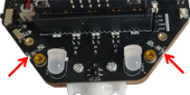
The changes in resistance are detected by the micro:bit and converted into a digital value in the range from 0 to 1023, where 0 means very dark and 1023 means very bright. The sensors are located at the front left and right of the chassis.


MEXAMPLE

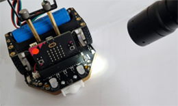
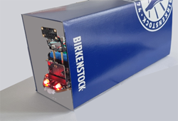
  Controlling robots with a torch
Use a torch to illuminate the right or left side of the robot. If the right light sensor measures a value greater than 250, the robot will turn right; if the left sensor is illuminated, it will turn left; otherwise, it will continue straight ahead.  

readLightIntensity(0) gives the light value of the right sensor.
readLightInternsity(1) gives the light value of the left sensor.

You may need to adjust the threshold value of 250 to suit the ambient brightness.

Program:

from mbrobot_plusV3 import *

setSpeed(30)
repeat:
    vR = readLightIntensity(0) #right
    vL = readLightIntensity(1) #left
    print(vR, vL)
    if vR > 250:
        rightArc(0.2)
    elif vL > 250:
        leftArc(0.2)
    else:
        forward()        
    delay(100)
► Copy to clipboard


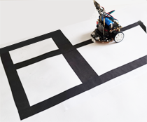
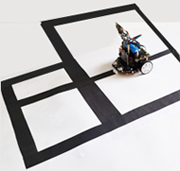
INTERSECTION DETECTION


mbRobot Plus V3 detects intersections: T-junctions, left-turn, right-turn and straight intersections. The intersectionDetecting() function returns 1 if the robot detects an intersection, otherwise 0.


EXAMPLE


With your simple programme, you can test how the robot detects the different intersections. You let it drive forward until it detects an intersection. Then it should stop.

The robot detects an intersection when the condition
if intersectionDetecting() == 1: or, in short,
if intersectionDetecting(): is True.
(Since 1 means True and 0 means False in computer science, you can omit ‘ == 1’).


Program:

from mbrobot_plusV3 import *

forward()
repeat:
    if intersectionDetecting():
        stop()
    delay(100)
► Copy to clipboard


REMENBER...


The Lidar sensor measures the distance to objects in front of it and provides a matrix with 64 measured values. Depending on the problem, you can use just one value, a list of values in a row, or a list of all 64 measured values.

With PID Control, you can move the robot forward or backward by a precise distance (in centimetres) or rotate it by an angle.

The light sensors allow you to measure the intensity of the ambient light. The measured values range from 0 to 1023. You will get higher values especially when you shine a torch on the sensors.

The intersectionDetecting() function returns 1 when the robot is at an intersection. To determine the type of intersection, it is best to use the irL2 or irR2 infrared sensors, which can detect the brightness of the surface next to the lane.


TO SOLVE BY YOURSELF


1.

Build a track and have the robot drive along it using the LIDAR sensor, as shown in the following YouTube video: VideoLIDAR


2.

Draw a track consisting of several 20 cm long sections. Use PID control to navigate the track accurately.


3.
Create a tunnel out of a cardboard box and let the robot drive through it. The robot should detect when it is in the tunnel and switch on its LEDs. After passing through the tunnel, it should switch the LEDs off again.  

4.
Create a track with stripes and crossings and have the robot follow specific paths.